AUGMENTED TAIL ROTOR SYSTEM
Augmented Tail Rotor System
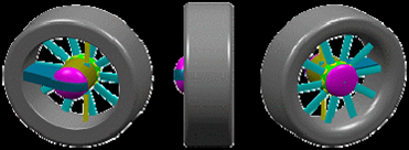
The conceptual design system uses a fan inside the tailboom to build a high volume of low-pressure air, which exits through slots and creates a flow of air along the tailboom utilizing the Coanda effect. This system augments the existing conventional tail rotor. The boundary layer changes the direction of airflow around the tailboom, creating thrust opposite the motion imparted to the fuselage by the torque effect of the main rotor. Augmented directional yaw control is gained through a vented drum at the end of the tailboom by the direct jet thruster. The system offers quiet and safe operation.
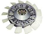
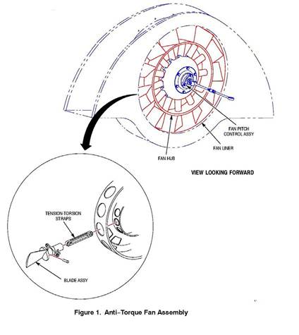
The anti-torque fan being considered is an axial fan with thirteen variable pitch blades. The fan provides anti-torque by furnishing variable flow of low pressure high volume air through the tailboom and thrusters. The fan operational rpm in flight at 100% power is 5,412 rpm. At 104% power, the fan rpm is 5,628.
Design Parameters:
- Fan Rotation Direction-Top blade afterward (TBA) direction makes the inflow dynamic pressure distribution uniform, so that aerodynamic and acoustic attributes are better.
- Blade Diameter- If large, low required power and high control power. If small, low weight and low hub drag. Diameter of the existing fan ranges 0.7m to 1.37m
- Fan Tip Speed- In forward flight, blade is unloading. Fin makes most of the anti-torque force. Advancing side problem is not critical. Around the main rotor tip speed is usually employed.
- Solidity-Ct/σmax and maximum thrust required determine a solidity. Range 0.5 to 0.56.
- Number of Blades-Aspect ratio is a main parameter. Even number is better for uneven blade spacing because of dynamics. Blades number ranges 8 to 12


