SW205T HELICOPTER PRESENTATION


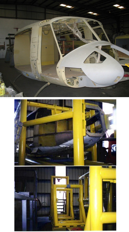
ASSEMBLY TOOLING
- Mainframe and tailboom fixtures in facility
- Annual laser calibrations approval by FAA
- Procured from US Army for UH-1 fleet
- Precision manufacturing and repairs
- No misalignment of airframe or tailboom
- Complies with FAA Airworthiness Directives for vertical fin spars.
THE HELICOPTERS
OVERHAUL SCHEDULE

LIFE LIMIT SCHEDULE

DIRECT MAINTENANCE COST

OVERVIEW SW205T
Upgrade Overview
UH-1/205 Upgrades that are included when producing the SW205T include the following items which are standard to all aircraft of this model:
- 212 Style Nose provides better flight characteristics and additional space for avionics
- Twin engines provide greater performance capabilities
- K-Flex Drive Shafts provide longer service life with higher reliabilities
- 412 transmission to support increased power at takeoff (1370 SHP) and continuous (1190 SHP)
- 212 Tail Rotor Hub Assembly provides 50% more tail rotor authority
- 212 Style Rotor Blades are wider and more efficient while providing higher performance (Option for Composite Blades)
- 412 90° and 42° Gear Boxes and Drive Shafts provide higher performance as well as longer time between overhaul requirements
- 212 Style Tail Boom (Incorporates tail boom baggage compartment as an option).
- High landing cross tubes provides more clearance when landing in undeveloped areas
Performance and Maintenance Upgrades Overview
The following performance and maintenance upgrades will be incorporated in the SW205T Helicopter:
- Electrical Wiring Updates and Power Module installation in Nose
- Engine Lube System Modification including an additional oil cooler blow as well as a heavy duty engine oil cooler
- Main Transmission Lube System Modification including additional oil jets installed for additional input quill
- 90° Gearbox Modification to 412 style to provide more tail rotor authority
- 42° Gearbox Modification to 412 style for increased safety
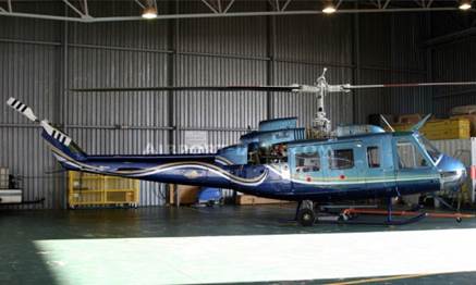
INTRODUCTION SW205T A High Performance Medium Twin Helicopter
INTRODUCTION
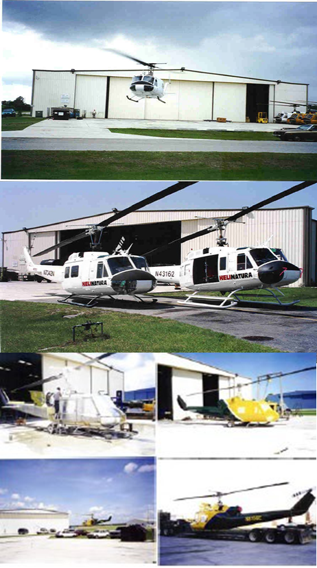
SOUTHWEST FLORIDA AVIATION, INC. is an enterprise dedicated to the development of efficient and cost-effective helicopters. The company draws on the many years of experience of its designers, engineers and production staff for each of its projects. SWFA is capable of producing, testing, manufacturing and supporting all of its helicopters anywhere in the world. For the SW205T project, SOUTHWEST FLORIDA
AVIATION, INC has entered into a sales and marketing agreement with Zeeland Aviation Corporation to promote and sell the SW205T Helicopters.
Executive Summary
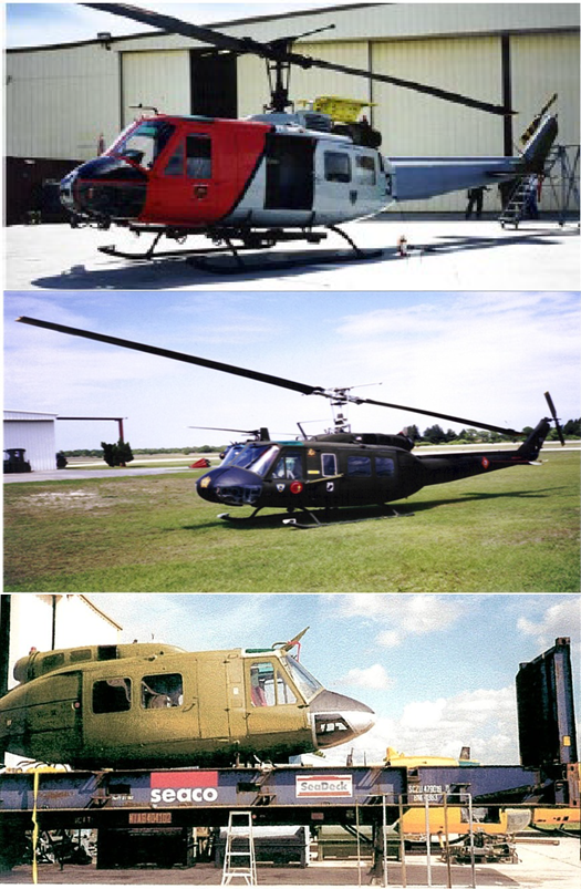
The SW205T is based on the 205 series and it’s counterpart, the UH-1H military version. More than 10,000 of the UH-1 helicopters have been manufactured since it’s introduction as it proved itself to be both reliable and efficient. The SW205T takes an greatly modified and enhanced version of the UH-1H aircraft into the 21st Century where it will operate more efficiently, safely and at lower cost than ever before. Equipped with two Honeywell T53-L-13B engines, the SW205T will outperform most comparable medium twin helicopters, and do so at a much lower initial acquisition cost as well as lower operating costs.
During conversion of the basic UH-1H/205 to the SW205T configuration the airframe is completely refurbished, with all major and minor components installed in either a new or overhauled condition. Additionally, the single engine is replaced by two T53-L-13B engines and an upgraded transmission providing higher speeds with longer range and lift capabilities. As a result of these upgrades the time between overhaul (TBO) for all major drive system components has been greatly extended. When the time between scheduled maintenance intervals is increased, the cost for maintenance decreases, as will overall operational cost per flight hour due to the increased aircraft availability. A variety of other upgrades as described later can be accomplished to specifically tailor each helicopter to the requirements of the operator.
POWER SYSTEM UPGRADES
The SW205T has several important power system upgrades which are described below
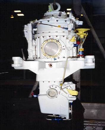
Twin Engine Installation
The engines are placed on the transmission deck at opposing sides of the transmission, exactly 180 degrees from each other. Each engine feeds power to the transmission via a separate driveshaft. This installation eliminates the need for a combining gearbox, thus reducing weight, cost, and complexity in the power train as well saving fuel. Jamie Hill holds the U.S. patent for this dual engine installation. Where most dual engine helicopters will not perform well on one engine, the SW205T will suffer no loss of performance on one engine. This will also allow the aircraft to have a major surplus of reserve power available. This will also increase the hot weather and the high altitude
performance.
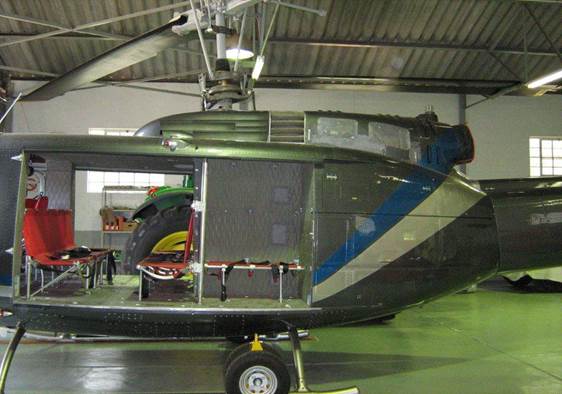
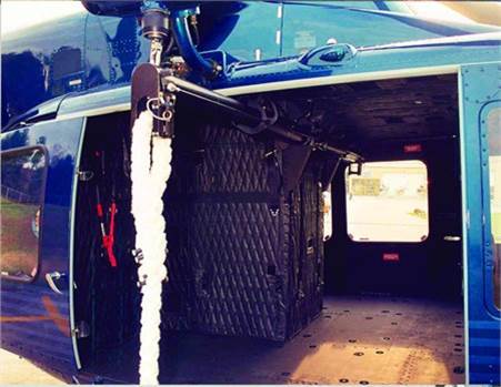
By having this excess of power available, the engines are not tapped out on torque or exhaust gas temperatures. This means that the engines can operate at a lower temperature internally, which in turn means less wear or damage to the nozzles or turbines. Additionally, by having this reserve power available, the pilot can either reduce the power of one engine to ground or flight idle or turn it off for long duration flights. The aircraft would not suffer any performance loss in this case and reduce fuel consumption. The cabin shall be modified as part of the dual engine support structure upgrade and Space Doors shall be installed. This modification shall result in an approximately eight additional cubic feet being made available.
Cabin will be modified by performing the following:
- Engine area is 30 inches wide extending forward off the face of the transmission pylon area;
- The passenger seating in front of the transmission pylon is relocated.
- Seating capacity remains the same;
- Construction is of FAA aviation quality.
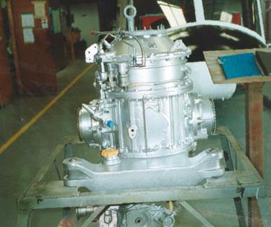
TRANSMISSION UPGRADES
Having the input of both engines at 180 degrees to each other reduces the stresses placed on the transmission. As this configuration has only one transmission input quill per engine and the input torque is 180 degrees apart, there is significant wear reduction to the internal parts of the transmission (Reference Figure 4). As a result the transmission will have a much higher Time Between Overhaul requirement of 6,000 hours.
The major upgrades will be in the Transmission area with the pylon area and landing gear mounts being reinforced. The transmission will be upgraded to the 212, UH-1W, 214 or 412 configuration depending on engines installed. The tail boom mounts will be upgraded to handle the additional toque available. After installation of a vibration monitor and an oil debris monitor, the transmission would be “On Condition” to determine TBO. The same arrangement can be installed to monitor the engine and drive train components, thus reducing maintenance costs and improving flight safety.
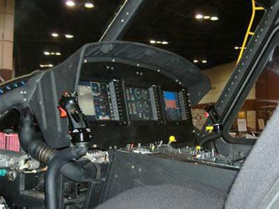
INSTRUMENT PANEL SW205T
Cockpit Instrument Panel
- The standard instrument panel will be modified to provide the following instrumentation supporting the dual engines.
- Triple Tachometer – 1 each
- Oil Temperature Gauge – 2 Each
- Oil Pressure Gauge – 2 Each
- NI Gauge – 2 Each
- EGT Gauge – 2 Each
- Torque Gauges – 2 Each

CHARACTERISTICS SW205T
SW205T Performance Characteristics.
The SW205T is an advanced version of the famous Huey helicopter which is a veteran of 50 years of service and remains in active service with the USMC as the UH-1Y Venom and AH-1Z Super Cobra. The basic design has been proven over the years.
We take this fine helicopter into a whole new era of accomplishment and capabilities by adding a second engine, beefing up many of the major components, increasing the maximum gross weight, adding lifting capacity while giving it a much longer range. All of this makes the SW205T a much more versatile machine capable of better service to the operator over a greatly extended spectrum of operational requirements. SW205T performance characteristics are compared in Table 2 below
The SW205T clearly outperforms any comparable medium helicopters available today, and does so at an initial cost of less than half of the competing helicopters while providing operators an operating cost that is much less than either recently designed helicopters of legacy Huey’s. This is possible due to advanced design and engineering techniques which incorporate the most recent technical advances into a highly successful marriage with the proven airframe and power plants of the Huey series of helicopters.
Figures provided in the Performance Comparison Chart (Table 2 below) are for the standard SW205T. Subsequent versions will incorporate short “wings” to increase the top speed and offload the rotor system. Supplemental fuel tanks will also be mounted, either internally or external on the wings to greatly increase the range for CSAR/SAR missions or other special long range mission requirements.
Given the additional power available with a second engine, the maximum gross weight will be increased incrementally in subsequent SW205T models as other modifications are accomplished to support the additional power. This translates into greater lifting capacity and an expanded operational envelope for high and hot environments. In the future, compliance with SWFA Technical Bulletins will increase gross weight to 18,000 lbs
SUMMARY SW205T
SUMMARY
The SW205T, is a very advanced version of the venerable and tested 205/UH-1H family of medium helicopters. Its capabilities far outreach any previous version of this famous line of excellent helicopters.
By mounting a second engine the helicopter now has more power which allows a much larger operational envelope and greatly expands its capabilities, regardless of operating conditions. The engines operate separately from each other entirely, and each are capable of powering the helicopter individually in any flight regime. This is an important safety of flight consideration.
The operating costs of the SW205T are substantially less than the legacy 205/UH-1H due to the use of components with longer times between overhaul, and with less stress and strain on the engines. The use of advanced technology in the redesign of certain aspects of the helicopter allows simplified solutions for the power train and flight control systems.
By using tested and proven off the shelf components in an innovative way, the SW205T is an inexpensive yet highly effective medium helicopter that has no rival in terms of cost-effectiveness among the current crop of modern medium helicopters.
In performance, the SW205T greatly outperforms the legacy 205/UH-1H, as well as the follow-on 212/412 models. It will out lift any of these helicopters throughout the operational envelope, with a longer range, and is more versatile in its capabilities. It can be outfitted for many different missions depending on the range of accessories and options selected.
A product of innovative and highly competent technical expertise, the SW205T is a helicopter for the 21st Century.
INTAKE SW205T
")

DETAILED SPECIFICATIONS


DETAILED SPECIFICATIONS

212 COMPOSITE NOSE
- The 212 composite nose offers more space for advanced avionics

- Your choice of fiberglass or carbon fiber construction.

UPGRADED ENGINE T53-L-703
- After more than 50 million flight hours, the proven T53-L-703/T5317 engine meets today's most rigorous reliability standards
- Provides 1,800 Shaft Horsepower (SHP) versus previous 1,400 SHP
- Time between overhaul (TBO) Standard 3,500 hours or can be increased to 5,000 hours at an additional cost


ALTERNATE ENGINES
- Pratt & Whitney PT6C-67D 1679 shp or PT6C-67E 1800 shp
- GE T700-GE-401C 1828 shp
- GE CT-7-2F1 2000 shp
- Rolls Royce (LHTEC) T800- 4N 1700 shp


TEDECO OIL DEBRIS DETECTION SYSTEM®
- Developed to help reduce aborts and unnecessary landing due to “fuzz chip detections”
- Has been 100 percent effective in detecting failures of oil-wetted components in engines and transmissions
- Has been proven to reduce aborts by 60%
- Proven failure detection between 25 and 100 hours before need to remove components


CENTRISEP-IBF
Engine Inlet Barrier Filtration System: The “fit and forget” Centrisep Engine Advanced Protection System shields the engine inlet from airborne contamination, which results in:
- Safer operation by protecting against sand and dust, foreign object damage (FOD), ice, and snow
- Increased operational availability
- Protection against engine erosion
DONALDSON-IBF
Engine Inlet Barrier Filtration System:
- Maximum engine debris/FOD protection which allows consistent flight operations and extends engine time. Improved protection over an inertial design and significantly better protection than a FOD screen.
- Pleated barrier filter element provides improved air flow versus inertial separation vortex/swirl tubes typical with IPS.
- Return on Investment (ROI): Less premature engine removals, meet expected engine TBO.
- Long-life filter assemblies, 4,500 hour (15 - 300 hour intervals).
- Reduction in corrosive salt air entering engine.
- Engine overhaul cost reduction due to elimination of erosion and contamination on all rotating and pneumatic components.
- Reduced maintenance time with improved plenum access.
- Common Line Replaceable Units (LRU) for mixed IBF fleets.
- Bleed air system maintenance eliminated with IBF.


UPGRADED TRANSMISSION
- Upgraded Transmission supports T53-L-703/T5317 or PT6C-67D engines
- Provides 6,000 hours Time Before Overhaul (TBO)
- Eliminates the need for a Combining Gearbox with our Modified 412 transmission for the SW205T
MAIN DRIVESHAFT
KAflex® Drive Shaft Upgrade
KAflex® Drives will be installed to provide the following advantages over previous drives:
- No Lubrication Required
- Increases misalignment capability
- Higher torque capability
- Higher damage tolerances
- Easier visual inspection
- Longer Service Life

ADVANCED MAIN ROTOR BLADES
212 Main Rotor Blades
The standard blade configuration will be 212 rotor blades. The use of 212 rotor blades due to increase lifespan and performance is the current trend in military helicopters. It should be noted that although the 212 rotor blades are available and suitable for military use, they have been certified by the FAA/CASA for use on civilian helicopters.


SW205T TYPICAL INSTRUMENT PANEL

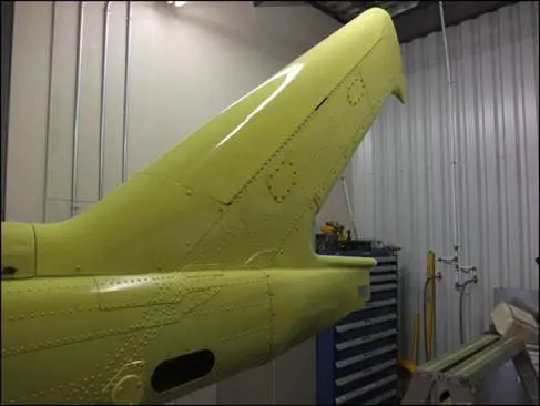
SPAR MODIFICATION
SWFA performs replacement of the fin spar in the following aircraft: SW Series, UH-1H, UH-1B, UH-1L, UH-1F, UH-1P and the Bell 204B, 205A-1, and 212. This modification is a Federal Aviation Administration (FAA) and a US Army Air Worthiness Release (AWR) approved terminating action for the spar FAA Airworthiness Directive (AD 99-25-12) and subsequent US Army Safety of Flight (SOF) compliance.
- Item 1 Replacement spar: this spar uses the Bell 412 spar cap
- Item 2 Replacement bulkhead: canted bulkhead (2 parts) was 0.015 to 0.025 thick each and is replaced by 0.032 thick bulkheads
- Item 3 Replacement shear tie: this replaces the previous shear tie that was 0.063 thick and is now 0.080 thick
- Item 4 Replacement skin: this replaces the previous skin that was 0.025 thick, and is now 0.032 thick
- Item 5 Replacement doublers: the left side is 0.032 thick and the right side is 0.040 thick, these doublers replace the previous 0.025 thick doublers
- Item 6 Skin: replaces the existing skin with skin and clips similar to Bell 212/412
- Item 7 Replaces the existing doublers with doublers similar to Bell 212/412Item 8 Replacement stringers: these stringers replace the previous 0.025 thick stringer (now 0.032 thick)
- Item 9 Added doubler (left side only): this additional doubler has been added to the left side only and is 0.040 thick
- Item 10 Added doubler: This doubler is 0.025 thick

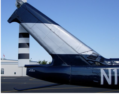
BLR FASTFIN®
- Performance Increases For SW Series Helicopters Equipped With Fastfin®
- SWFA Helicopter Uses Fastfin ® System as standard equipment on new production aircraft
BLR STRAKE KIT™
- Upgrade Provide A Dramatic Increase In Tail Rotor Authority With A Decrease In The Power It Takes To Maintain Directional Control
- This Means More Available Power To The Main Rotor, Which Increases The Altitude And High Temperature Performance Of The Aircraft
- These Benefits Are Accomplished Without Modifying The Original Drivetrain or Gearboxes In Any Way


SAFT BATTERY
- 53 AMP-hour Ni-Cad Battery with increased amperage than the standard 40 Amp battery.
- 53 AMP-hour Battery Kit
- Dual Battery Provision are accommodated
Battery-driven engine starts with the standard 40 Amp-Hour battery are limited to aircraft cold-soak temperatures above 0 °C (32 °F) For battery-driven engine starts down to aircraft cold-soak temperatures of -25 °C (-13 °F) a 53 Amp-Hour battery is required. If configured, the 53 Amp-Hour Battery kit must be installed prior to, or concurrently with the installation of the SW-Series certification.
MISSION CAPABILITIES
- TRANSPORT
Look no further than SWFA helicopter for transport needs. With aft cabin seating for 11 passengers or 14 passengers in high density seating, the SWFA helicopter works as diligently and reliably as the occupants do. This medium lift helicopter has a large flat, re-configurable floor area for multi-mission cargo needs. Multiple structural fittings and hard points allow for flexibility in seating arrangements and attachment of equipment to meet transport and cargo operations. The SWFA helicopter has the space and the lifting capacity to get the job done.
- PARAPUBLIC
The SWFA helicopter was built for the parapublic mission. With special operational equipment available, the aircraft can be configured to meet your mission needs: command & control, patrol, firefighting and tactical insertion/extraction. The fuselage features multiple structural fittings and hard points, two swing-out jettisonable crew doors and two aft cabin sliding doors with two emergency exit panels on each door. The sliding doors latch open for in-flight operations. Two swing-out doors allow extended access to aft cabin. These features keep the team safe so that they can keep the public safe.
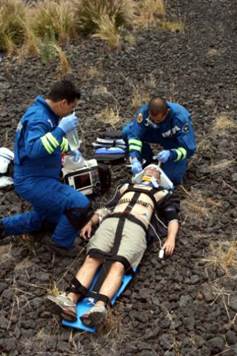
- HELICOPTER AIR AMBULANCE
The SWFA helicopter was built on a strong history in emergency life-threatening situations. The cabin sliding door and panel door on each side of the fuselage provide unobstructed openings. Its cabin can carry litters. The wire-strike protection system is designed to offer a proven measure of protection against horizontally strung mechanical, electrical and communication wires and cables. When you are the help on the way, the SWFAhelicopter provides greater capacity enabling faster mission accomplishment.
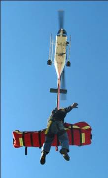
- SEARCH AND RESCUE
For search and rescue missions, the SWFA helicopter provides a stable hover platform with excellent fore & aft center of gravity tolerance and lateral stability. Large wide door openings enable easy cabin access and room to maneuver for hoist operations. Single-engine fuel efficiency allows for greater search time and range. Optional auxiliary fuel tanks increase the standard search range capability. When you need to search, look no further than the SWFA helicopter.
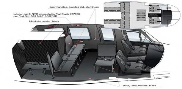
TRANSPORT SEATING
DESCRIPTION
- The standard seats are of tubular construction with reinforced canvas webbing for support areas. The seats are attached to the floor and transmission support structure. Seats can be installed for rescue missions, then folded and stowed flat; or they can be folded for cargo missions as required.
ARRANGEMENT
- Standard seating is eleven passengers that can be seated in the aft area of the forward fuselage section. Three seats facing forward, and accommodating five passengers, may be placed across the cabin immediately forward of the transmission support structure. A one-passenger seat, without a back rest, is located between 2- place seats which have backs. Two, 2-place seats, without backs, are located aft of the five-passenger seats parallel to the helicopter center line. Passengers in these seats face outboard. Two single passenger folding seats, facing aft, with backs, are located just aft of the crew seats. Fourteen passengers can be seated with high density arrangement as seen in photo top right or six VIP arrangement in photo below right.
SEAT BELTS
- Individual lap-type seat belts are provided for all seats. These same belts, with web extensions, are provided for litter patients when helicopter is used for rescue missions.


FIREFIGHTING
BELLY TANK SYSTEM
- Tank Assembly: External belly-mounted fiberglass and aluminum tank mounted to external hard-points. Tank attaches with quick-release pins for fast and easy installation.
- Refill Pump: Electrically driven, with in-flight pump and hose assembly emergency release capability
- Dump Doors: Electrically actuated, hydraulically operated. Fail safe system; doors will open with the loss of electrical power. Door selection switch allows for separate operations of each door for longer drops.
- Cyclic Control: Allows pilot to control loading, mixing, dump volume and drop length.
Typical Specifications
Net Weight: 416 lbs.
Gross Weight: 3342 lbs.
System Capacity: 350 gallons
Chemical Capacity: 27.2 gallons
Power Requirements: 24VDC
Amperage Draw : 90A
Hover Fill Rate (max): 270 GPM
Hover Fill Time (probe submerged): 55-75 secs.
VNE (water drop): 70 knots VNE (empty, pump stored): 110 knots


FIREFIGHTING CONT’D.
Bambi Bucket System
- Vendor supports firefighting operations in over 100 countries
- All equipment and supporting material (buckets, foam, etc.) readily available
- Bambi Bucket – lowest cost, easiest to deploy, can hold up to 320 gallons of water
- Can be filled either by dipping into water source or by sucking water with minimum depth of 50 cm.
- Fire retardant can be added from helicopter internal dispenser to water in bucket

TACTICAL MISSION
- The Fast Rope Insertion/Extraction System provides aft cabin mounted hardware consisting of a quick deployable tube and support assembly designed to allow rapid insertion of special operations personnel from both sides of the aircraft utilizing a specially designed rope. The Fast Rope System incorporates an innovative telescoping feature to allow quick retraction of the tube ends into the cabin to allow operation of the aircraft with cargo doors closed. The kit also includes an innovative quick release rope retention mechanism allowing crew to release the rope in the event of an emergency. The system allows four personnel per side simultaneous deployment.
- Cabin Armor Areas of Coverage
- Cockpit (floor and doors)
- Cabin (floor and walls)
- Chin bubble
- Crew Seats- bottoms and backs
- Gunner stations
- Transmission Walls
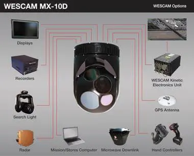
TACTICAL SURVEILLANCE
IR/EO CAMERA SYSTEM
Low-altitude Tactical Surveillance & Target Acquisition and Designation missions requiring low-weight installation flexibility.
Product Features & Benefits
Compact Solution
- 43 lb../19.5 kg turret
- 15 in. turret height for better ground clearance
Multi-Sensor Imaging/Lasing Payload Options
- Currently supports up to six sensors simultaneously
- Superior HD imaging resolution from Electro-Optical (EO) camera
- Laser rangefinder, illuminator, designator
Latest Enhancements – 2020
- WESCAM Advanced Video Engine (WAVE)
- High Sensitivity Color Camera
- High-Definition (HD) IR
- Pseudo-Colour IR
- Advanced Video Tracker (AVT)
- Embedded MTI
Enhanced Local Area Processing (ELAP)
- Real-time image enhancement for EO day, EO night & Infrared
High-Performance IMU & MX-GEO Software Suite
- IMU & MX-GEO work to create accurate target location
- MX-GEO automatically aligns to the aircraft
- Robust automatic image focus
Uncompromised Stabilization
- Four-axis gimbal with internal IMU
- All payloads are fully stabilized


AIR AMBULANCE
Air Ambulance Technology GmbH designs and manufactures interiors for, and with its customers. The medical carrier of the rotorcraft can be designed with either new medical devices or already owned medical devices. The interior can be transformed from a 1 patient to a 2 patient configuration within minutes
The installation time for the 2 patient full EMS configuration for the rotorcraft is approximately 20 minutes. There are three possible configurations. 1 patient, 2 patient and SAR. Not only are Air Ambulance Technology GmbH's aircraft interiors exceptionally quick to install and remove, the modular system also allows the operator to change between a full EMS and a Search and Rescue mission within a very short time.
AIR AMBULANCE CONT’D.
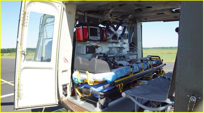
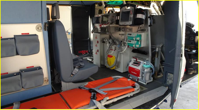


- Customized for customer
- Typical stretchers for 1-2 patients
- 2 Medical crew seats
- Support medical electronics such as suction, ventilation, Oxygen station, medical power distribution, EKG monitor, etc. for 1-2 positions
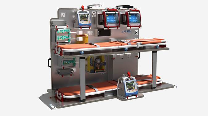
- Optional Features may included:
- Instrumentation for intensive care patient transfer
- Transport incubator (Isolette for neonatal patient transfer
- Certification: FAA/CAA Supplemental Type Certificate (STC).
System Overview:
- Quick change capability can be installed or removed from aircraft in less than 15 minutes and requires minimal modifications to the aircraft
- High quality, durable design and cost-effective installation
- Built aircraft-specific and customer-specific
- Allows for a variety of custom medical mounts and patient loading accessories
Single 2800 Series System Install
System Features:
- Fully self-contained and lightweight
- 3500 liters of oxygen, dual air compressors, vacuum pump and - 1000 watt inverter
- AC outlets, DC outlet and dual pneumatic outlets - Custom stretcher specifically designed for patient comfort
- Multiple IV Mounts
Spectrum Aeromed System Options:
- 2800 Series System
BASIC EMS CONFIGURATION PRICING WILL VARY FOR ADDITIONAL ITEMS CUSTOMER REQUIRES


SEARCH & RESCUE
INTERNAL HOIST
Helicopter owners seeking superior performance, reliability and capability - as well as low cost of ownership – can count on Collins Aerospace’s Goodrich rescue hoist. Internally mounted, electrically powered rescue hoist model 42305 utilizes the Collins Aerospace proprietary translating drum cable management system. The hoist design also incorporates a Weston-style load brake for added safety. The lubricated cable extends cable life and helps arrest corrosion of the cable.
KEY BENEFITS/FEATURES
- Capable of high fleet angle allowing hoist operation in high winds or other circumstances requiring an off-angle lift
- Single point payout reduces potential for hoist-induced load swings
- Continuous operational duty cycles allow for multiple victim rescues without a cool-down period
- Worldwide field engineering services available
DESIGN FEATURES
- Boom rotates 205 degrees for easy deployment and recovery of a stretcher
- Cable extension meter on control pendant
- Hour meter logs total hoisting time
- NVG compatible (42305-3 and -5)
- Secondary hoist controls for pilot
- Emergency cable cut with press-to-test feature
- Redundant limit and decal switches
SEARCH & RESCUE CONT’D.
EXTERNAL HOIST
The Breeze Eastern externally mounted 600 lbs. rated 28 VDC electrically driven hoist incorporates all of the safety, self-sensing and redundancy features, as well as the cable management system present in all other Breeze Eastern category one hoist designs. These features enhance operational safety and unit reliability and extend the service life of the hoist assembly. The hoist is normally operated by a crew-person through a variable speed control in a hand-held control pendant assembly or control box. A second set of controls for the hoist is located on the helicopter cyclic stick. These controls are operated by the pilot and have priority over the crew-person controls.
DESIGN FEATURES:
- External, electric hoist
- 30º fleet angle
- Continuous duty cycle
- Lubricated cable extends cable life and resists corrosion on internal metal components
- Event meter logs total cycles (hour meter available on some models)
- Emergency cable cut
- Down limit override for quick cable changes
- Redundant limit and “decal” switches
- Dynamic braking available on some models
- Night vision compatible controls
- Cable length display on operator’s pendant
- Searchlight or hover control pendant
- 2 position Intercom switch on pendant
- Pendant lighting includes “Overtemp” or “Caution” indicators
- Priority hoist controls for pilot


Operations May Require
- Finding the victim in bad weather
- Treating victim at site before airlift
- Retrieval under hazardous conditions
- Weather
- Forestation
- In Water or At Sea
- FLIR
- BASKET
- NIGHTSUN SX16 SEARCHLIGHT
- 600 LB EXTERNAL H0IST


GROUND SUPPORT
Forward Logistics Support
U.S. Army Manual ATP 3-04.97(1/26/2012) established the techniques for forward arming and refueling points. Commercial and military systems to meet the guidelines and requirements are readily available for:
- Transport of Fuel to forward logistics supply point
- Transport refueling bladders
- Transport pumping systems
ACCESSORIES


SPACEDOOR™
If installed, you can increase visibility and add 8-12 inches of usable space in your cabin area. The Spacedoor™ allows you to have a variety of possible interior configurations to meet your needs — whatever they are. This is a great accessory for multi-mission aircraft. Designed to replace the standard OEM sliding door, the Spacedoor™ utilizes a lightweight composite technology. It’s easy to install and does not create additional operating limitations. Here’s another bonus: The Spacedoor™ comes with one of our other products, the Cabin Door Roller Kit, which makes opening and closing the door a breeze.
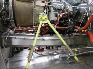
ADJUSTABLE ENGINE MOUNTS
Eliminates hours of frustration when using an Adjustable Engine Mount Kit.
- Reduces time to complete engine alignment
- Quick installation
- Modify your existing engine mounts (mono, bi, tripod) with turnbuckle


CABIN DOOR ROLLERS
The Cabin Door Roller Kit allows newly fitted cabin doors to slide with minimal effort.
Two roller bearings on both the horizontal and vertical axis of the bracket ensures a better supported door that rolls more easily. The Cabin Door Roller Kit also increases the life of the tracking system, with longer lasting stainless steel rollers with replaceable plastic caps and a segmented lower friction track to avoid metal on metal contact.
CAP ASSEMBLY BUMPER KIT
The new Cap Assembly Bumper Kit includes two polyurethane bumpers to replace worn OEM rubber bumpers on the crosstube cap assemblies. The bumpers are constructed of durable polyurethane and feature flanges to lock the bumper to the strap. This simple to install kit is a cost effective and more durable solution for worn OEM components.

AUXILIARY FUEL SYSTEM
External Auxiliary Tanks:
Two externally mounted Kevlar® fuel tanks providing an additional 140 gallons of usable fuel, extending endurance by 1.5 hours. This system is compatible with internal auxiliary fuel system for military and commercial aircraft and is compatible with OEM float systems. Complete utilization of 13 passenger seats, or all cabin volume for cargo.
Internal Auxiliary Tanks:
Two internally mounted aluminum fuel tanks providing an additional 280 gallons of usable fuel, extending endurance additional 3.1 hours.


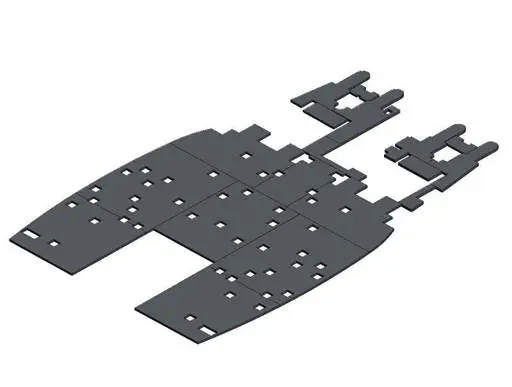
CABIN PROTECTORS
- Durable, lightweight protection for the cabin cargo area honeycomb flooring. CNC cut for superior fit.
- Constructed of high density, impact resistant aerospace grade polycarbonate that will not warp or crack from extremes of heat or cold.
- The Aft Cabin Wall & Pylon Protector Kit consists of four aerospace grade polycarbonate components that are installed into existing nut plates in the aircraft aft cabin wall and pylon. The purpose of the aft wall and pylon protectors is to protect the expensive honeycomb from damage. The aft wall and pylon protectors feature a multitude of cut-outs for compatibility with the passenger seating and equipment installation and install under the existing blankets so they will not alter the look of the cabin.
WSPS
WIRE STRIKE PROTECTION SYSTEM
The Cable Cutters Kit provides a means of protecting the helicopter during a wire strike by providing the capability to cut a cable or wire before catastrophic damage occurs. The kits are designed to reduce the possibility of a cable or wire entering the cockpit and to reduce the chance of flight control damage. Similar cable/wire cutting devices have proven to be effective even during multiple wire strikes. The kits incorporate both an upper and lower cutter and each cutter is designed with high strength cutting blades. The Apical cutter design are tested to verify the capability to cut a cable having a 14,000 lb tensile strength. The kits are configured for medium helicopters with standard or high landing gear. An optional GPS Antenna Mount Kit is also available, which allows placement on the upper cutter deflector for ideal positioning of the antenna.


HIGH SKID GEAR
Landing Gear Kit – Extended Height 39”
Extended Height Landing Gear kits provide extra ground clearance for the installation of water bombing tanks and other belly- mounted equipment. These specialized landing gears are only available from DAS. SW205T model are approved for maximum gross weight of 12,500 lbs.
EMERGENCY FLOATS SYSTEM
TRI-BAG FLOAT SYSTEM WITH LIFERAFTS
Kit includes Fwd, Mid & Aft Tri-Bag floats with integrated liferaft in the Mid floats. Requires installation of 412-630-033/-034 Steps.
KEY FEATURES
- Exchange program available
- Available with integrated liferaft (10-man)
- Requires installation of D412-630-033/-034 Steps
- Hoist compatible configuration available
- Installs on high gear
KEY BENEFITS
- Lighter than OEM
- Includes 10-man integrated liferaft
- No life limit on inflatables (Floats & Liferafts)
- Best in the industry lead time
- Increased safety with electrical/mechanical & water sensor activation system
- Reduced maintenance cost (longer maintenance intervals)
- Tri-Bag technology allows for:
- Significant weight reduction (smaller reservoir & less gas usage)
- Increased stability - Can install on OEM compatible skidtubes
- Liferafts will be compliant with EASA OPS requirements


PILOT WINDOW GUARD
The pilot window guard protects the green house window from accidental breakage when maintenance crew climb onto the roof deck.
AVIONICS CONSOLE
This easy-to-install riser panel allows for the installation of a greater variety of avionics instrumentation. The design of the riser allows the operator a wider range of equipment locations.


DRIVESHAFT TUNNEL KIT
Extra clearance at Fwd section of drive shaft tunnel
- Reduced maintenance costs and frustration
- Provides additional clearance compared to OEM design
- Reduced possibility of the driveshaft contacting the fireshield during operation
- Center section can be removed for extra clearance during starter maintenance
- Accommodates larger diameter driveshaft
- Panels are individually replaceable to further reduce costs
- The Drive Shaft Tunnel Kit is designed to reduce maintenance costs and frustration. Removal and re-installation of the drive shaft is eased by providing additional clearance compared to the OEM tunnel to ease drive shaft alignment and accommodate larger diameter drive shafts.
DUAL CARGO MIRRORS
The dual mirrors are fixed onto a bracket installed along the rivet lines on the nose of the aircraft, and provide better viewing of the cargo hook for pickup and release from both pilot and co-pilot positions.
- Mirrors are now adjustable
- D212-580 mirror now has multiple installation
- locations for improved viewing
- Also available: LED Pulse Lights
- Preferential pricing available when purchasing both
- Dual Cargo Mirror & LED Pulse Light—Contact Sales


CREW DOOR STRUTS
The Automatic Door Opener Kits modify the hinge panel (quarter) doors with a durable gas spring that assists in opening the door and keeps it open while occupants are entering the aircraft.
- Reliable gas spring
- Gas Spring does not force the door to travel past its normal open position
- Prevents door from swinging closed as passengers enter or exit the aircraft
- Compatible on aluminum and Spacepod™ doors
PROTECTIVE TRIM
Protective Trim Kits
Protective Trim Kits feature stainless steel doublers that protect aircraft skin and structures in often damaged areas. Door Sill Protective Trim Kit is designed to protect the crew door sills from damage. Step Protective Trim Kit consists of
two stainless steel doublers that install around the RH post steps between the crew and hinge panel doors to protect the edges of the aircraft skin from damage. Fuel Panel Protective Trim Kit consists of a stainless steel doubler that protects the aircraft skin below the aircraft fuel cap from fuel cap damage during refueling.


VIP INTERIOR


AC SYSTEM
This innovative, lightweight and compact design uses the latest technology to create smaller and lighter components while still providing the same performance and reliability. All the major components of the system are located on the transmission deck for ease of maintenance, increased cooling efficiency, and to help reduce weight. An electric motor allows the AC to be run from external power. The Air Conditioning System consists of: a compressor and electric motor attached to the helicopter’s transmission, a condenser and evaporator unit attached to the transmission deck, and the necessary parts and hardware to complete the kit installation. The Air Conditioning System is powered by a drive pulley attached to the Transmission or during ground operations, the AC system can be run from external power. The system reduces weight by having a single evaporator and condenser on the transmission deck in close proximity of each other. The A/C system also has multiple speed output control and fresh air ventilation.
- Lightweight
- Compact design
- Cools down before take off


AIRCRAFT COVERS
- Engine/Window Covers Made of our custom layered laminated material. The outside layer is made of a Nylon Codura which is water repellent, breathable and reflective. The inside layer is a dust-proof soft inner lining. All engine and window covers are sewn on with a green (right side) and red (left side) indicator patches, for ease of installation. Available in light-grey or red.
- Insulated Covers-A custom quilted layered material. Insulated covers are made up of a ½” felt layer with a reflective silver lining (helps keep the warmth of the engine inside) between two layers of Nylon Cordura. Available in black or red.
- Main/Tail Rotor Blade Covers Our blade covers are made of two different types of material: Medium weight Nylon (Recommended for Summer Use), Available in Red Only. Heavy weight Tarp (Recommended for Winter Use), Available in Silver or Black
- Blade Tie-Downs/Intake Covers All our blade tie-downs and intake covers are made of a Heavy-duty Polyester Scrim, all sewn on and secured with heavy duty nylon webbing or bungee hooks.
- Engine/Exhaust Plugs Made of a Polyester acrylic fabric, this material has a rough grip for a secure tight fit. Water Repellent and Stain Resistant.
- Pitot Tube Covers
GROUND EQUIPMENT
- Ground Handling: Wheels are designed to make the repositioning of grounded aircraft a much easier task. The dual wheels reduce twisting and strain on the skid tubes, as well as providing equal pressure on both sides of the skid tube when raising and lowering the helicopter. Ground Handling Wheels are available in Hydraulic and Mechanical models for a wide variety of aircraft and are also available as lightweight, carry along wheels for emergency situations when away from home base.
- Tow Bars: Towing systems are designed for one-man operation and are simple to use. They don’t interfere with equipment mounted under the helicopter and can be installed in three to five minutes. The caster wheel assembly can be used separate from the Towbar if desired. The Towbar can also be attached to most towing vehicles. The Hobart GPU-400 and GPU-600 Solid State ground power units provide precisely regulated 28.5 volt DC service with minimum noise.
GPU: These reliable solid state GPU’s are equipped for engine starting in the current limiting “soft start” mode recommended by most airframe manufacturers. Specifically developed in response to customer needs, the GPU-400 and GPU-600 supply the fully regulated, dependable power required by today’s more demanding aircraft. The GPU-400 delivers 400 amperes continuous to 1600 amperes peak for starting, and is available with a 14.25 volt DC option. The GPU-600 delivers 600 A continuous to 2000 amperes peak for starting.
Performance Features:
- Output DC voltage independent of ±10% input voltage variations
- Output current limit setting is adjustable over the range of
150 to 1600 amperes for GPU-400;
300 to 2000 amperes for GPU-600 - Output terminals safely located inside case
- Separate input and output contactors with status indication lights
- Convenience receptacle for lights, electric drill, or test instruments
- T-handle 3-wheel mounting with activated parking brake provides easy maneuverability and stable parking.
- DC output cable


CARGO HOOK KIT AND NET
Cargo hook kit includes many technological improvements over the original Bell equipment. They offer reduced maintenance costs while improving utility and safety. Our cargo hook kits include TALON MC Keeperless Cargo Hook, which has significantly more safety features than other hooks available.
Note:
- 5VDC back lighting system for C-39 indicator
Benefits
- 30% Lighter than Original Bell System: Lighter, stronger alloys and parts allow the system to haul maximum weight, while adding minimum load to the airframe.
- Improved Yoke Design: We've eliminated cracking problems by distributing load stress across multiple parts.
- High-Impact Bumper Ring: Crack-resistant, 2-piece polymer ring protects both hook and airframe from the stresses of swinging loads.
- Nickel Plated Carbon Steel Load Beam: We've upgraded the load beam material from stainless steel to nickel plated carbon steel for greater durability. The new load beam is harder and resists wear and tear from frequent use for heavy loads.
- Power for Suspended Equipment: The 8-channel slip ring supplies power to your suspended equipment.
- Integrated Onboard Weighing System: Allows pilots to instantly know the exact weight of the cargo on the hook. Reduces the risk of overload airframe stress and helps the pilot make more informed aircraft loading decisions.
- Keeperless Hook: The keeperless hook handles a wide variety of load ring sizes and styles while eliminating the possibility of losing a load that inadvertently gets past the keeper.
- The Onboard Advantage: Our cargo hook kits can be installed on new or existing aircraft using standard hand tools. Time between overhauls is five years or 1,000 operating hours for all cargo hooks. And because Onboard Systems maintains a large inventory of cargo hook kits and spare parts, we can usually ship your order out quickly.
- Increase productivity, safety and accurate external load weight reporting with a digitally-accurate weighing system from Onboard Systems. This load weigh system is designed to integrate seamlessly with cargo hook system for your 204, 205, 212 or 412 helicopter. Lift with confidence every time while safely increasing your average loads and improving operational efficiency.
Benefits
- Highly Accurate: Digital technology in the weighing systems ensures consistently reliable measurements
- Safely Lift Higher Average Loads: Ramp up productivity by eliminating guessing games about the weight of your load. When the pilot knows the exact weight being carried, there's no need to err on the side of caution.
- Includes All Hardware: All necessary hardware for a full installation is included. Comes with the load cell, cockpit indicator, and wiring harness.
- Improve Customer Relations: Eliminates disputes over weight promised or weight transported. You can report accurate statistics to your customer right away.
- Reduce Maintenance Costs: Never make load weight miscalculations again. Your pilots will know the load weight every time and greatly reduce repairs from airframe overstress and overload.
- Digital Readouts in the Cockpit: Provides a clear, backlit, easy-to-read digital weight readout in pounds or kilograms. Easy to operate without increasing pilot workload.
- Scaleable Analog Output: Built-in 0-5 volt output can be used to feed data to a variety of Helicopter Flight Data Monitoring (HFDM) devices (such as a Hobbs meter, Latitude, or Flightcell data recorder, etc.). Signal can be used to alert the pilot if a load is on the hook, or provide load weight information to a data tracking or GPS system.
- NVG Backlighting Option:
EXTERNAL LOAD EQUIPMENT
Cargo hook external load equipment includes many technological improvements over the original Bell equipment. They offer reduced maintenance costs while improving utility and safety.
Overall Benefits:
- Extended Shelf & Service Life: Recent product design update and extensive airworthiness analysis now allows for a combined shelf/service life of up to 10 years for products manufactured after February 1, 2020. For products manufactured before February 1, 2020, please refer to shelf and service life information on the product ID tag.
- Protective End Covers: Provide abrasion resistance at both ends of the longline (top and bottom). Reflective cinch strap promotes high visibility.
- Compliances: Supported by Airworthiness Analysis to FAA CFR Title 14, Parts 27 & 29.
- Proof-loading: Proof-loaded to working load limit (WLL).
- Comes With: Permanent ID tag, Certificate of Compliance (COC), transport/storage bag, and user instructions manual.
- Optional Accessories: Contact us to request custom line lengths or hardware (such as a non-electric swivel hook for bottom end), weighted bottom end-covers (for increased load stability and velocity without load), or other accessories.
Longlines
- Longline kits for HEC missions include many essential components for properly rigging your aircraft to carry human external cargo, including the Y-Rope, a rigging plate, longline, weight bag, lanyard, and carabiners.
Rigging Plate
- HEC Rigging Plate helps you manage distribution of up to five separate loads for connecting multiple lanyards during your mission. Four of the holes are rated up to 310 lb.. each, while the center lug is rated for up to 800 lb.. Any combination of loads may be applied through the lower five holes as long as the 310 lb.. load is not exceeded when using each of the side holes and the 800 lb.. overall limit is not exceeded.
Slip-Ring Kit
- Tangled wires and complicated operations with suspended auxiliary equipment are things of the past when you install the Onboard Systems Multi-Channel Slip-Ring Kit. Our Slip-Ring Kit supplies electrical power and control signals to accessory equipment suspended from the rotating cargo hook. Equipment suspended from rotating hooks receive full, direct power, while the hook itself is allowed to rotate freely, unhindered by snagged power cables coming from other parts of the aircraft.
Cargo Hook Retention System - The Cargo Hook Retention System was designed for Bell 205, 212 and 412 operators who need to be able to temporarily keep the cargo hook assembly from rotating during certain types of external load missions. This certified upgrade kit provides a restraining arm that is coupled to the cargo hook assembly and supported by a bracket that is attached to the airframe. It can be quickly enabled or disabled as needed via a quick release ball lock pin.
Benefits
- Stops Cargo Hook Rotation: Length of rod allows for full fore/aft and full lateral movement without hook rotation. Rod is supported by a Teflon® lined bracket that lets the pole smoothly swing forward and back.
- Supports Complex Missions: An elegant solution for situations where you don't want the hook to spin due to multiple cable connections, use of seeding buckets, cone harvesters, portable saws, hydraulic shears, Sacksafoam™, hydraulic pumps, etc.
- Quick & Easy to Use: Once the kit is installed, you can leave it on the aircraft and enable/disable it as needed for each mission via a quick release pin.
- Simple Yet Robust System: Requires minimal maintenance. Service on condition.


PORTABLE OXYGEN
The HPASOS system has been specifically designed to meet the needs of unpressurised airframes flying at altitudes in excess of 10,000ft providing the pilots and aircrew with protection against the effects of hypoxia.
It is the most efficient and easy to use system available, not batteries required.
The Oronasal Mask Assembly has been designed in conjunction with the POD Unit, again as a key component of the HPASOS system. The mask comes with a fully integrated communications suite allowing voice communications over the existing aircraft network. The mask also benefits from a fully adjustable helmet interface which allows the user to quickly and easily drop the mask off the face when the aircraft is flying at an altitude where oxygen is not required, below 10,000ft.
The Pneumatic Oxygen Delivery Unit is one of the key components of the Helicopter Pilot and Aircrew Supplementary Oxygen System (HPASOS). The system has been designed specifically for the pilots and aircrew of unpressurised rotary wing aircraft, giving them protection against the effects of hypoxia when flying at altitudes in excess of 10,000ft.
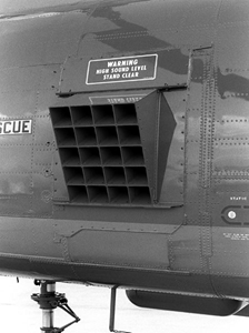
LOUD SPEAKERS
The AA21-400 Cabin PA control unit provides centralized control for an aircraft’s internal and external PA systems. The integrated 25W amplifier drives an 8W speaker arrangement for internal cabin paging. The AA21-400 provides excellent high quality sound, a very important feature when the audio is to be amplified by an external, high power PA system.
The LSA Series is newest Loud Speaker Amplifier. This high end ‘Class D’ amplifier will outperform any comparable system on the market today. Using the latest technology allows for a lighter weight PA that processes and optimizes the audio signal to get the best output using much less power compared to its predecessor. Newer generation parts and automated electronic assembly also allows for a better price point, reducing the cost to the end user. The LSA Series of amplifiers incorporates a ‘smart power supply’ that modifies the amplifier output to meet the output load demand. These amplifiers deliver up to 1200 watts of audio output power to the speakers.
The TS95-16DS is a 6 bell, high power speaker with a steel chassis that provides magnetic shielding. Fitted with AEM’s updated high power speaker drivers, the TS95 series speakers provide much better conversion of electrical power (Watts) to sound pressure (SPL). Designed from the same mechanical configuration as the TS9x series speakers, the TS95 can be installed into existing PA installations with only minor mechanical modifications to the aircraft speaker mount.


ADVANCED TECHNOLOGY


ASPEN GLASS COCKPIT
ASPEN Cockpit Display System (Standard on SW205T)
Overview
The Evolution™ 2500H combines the powerful 1000H Pro PFD (Primary Flight Display), the 1000H MFD (Multi-function Flight Display), and the 500H MFD to deliver Aspen’s total glass cockpit solution. The 1000H Pro PFD and 1000H MFD provide the safety and confidence of total PFD redundancy. The 500H MFD expands display area to put more flight data where you want it - the way you want it. Aspen makes the total glass cockpit experience for helicopters both easy-to-use and affordable with patent-pending retrofit technology and superior compatibility for substantially lower installation costs and total cost of ownership.
The 1000H Pro PFD provides professional-grade EFIS primary flight instruments, a full-featured electronic HSI, and moving maps. The 1000H MFD doubles your panel’s display area and delivers full redundancy of critical systems and sensors. The 500H MFD rounds out the package to deliver the largest display area and most flexible glass panel on the market. All that display area also allows you to view your approach chart and moving map at the same time - cross check your position with ease!
The 1000H MFD incorporates the exact same hardware and software as the PFD, so these units give you two of everything, not just two displays: dual independent AHRS, Air Data Computers, compass systems, HSIs, and more.
With Aspen’s exclusive full PFD redundancy, if your PFD fails you simply press the 1000H MFD’s REV button and it becomes the PFD - converting into an identical backup right in your primary instrument scan. This identical PFD backup means less stress and potential confusion in a pressure situation. No other helicopter glass cockpit system gives you this level of redundancy and confidence at any price!
The Evolution 2500H Package delivers value pricing compared to installing the 1000H Pro PFD, 1000H MFD, and 500H MFD separately. Evolution Flight Displays are fully upgradable, so you can add comprehensive hazard awareness capabilities and other new features via software upgrades, without removing displays from your panel.
Evolution 2500 Package - your ultimate glass panel.


ASTRONAUTICS GLASS COCKPIT
Overview
Astronautics develops custom displays to meet unique customer requirements. These displays have been RADAR/Terrain following displays, Upfront Control Panel displays, Engine/Hydraulic/Fuel Flow displays, Electronic Warfare displays, Mission Station displays, and Aft Seat HUD Monitors. Configurations have included customized AMLCD sizes, mechanical packaging to meet challenging installation requirements, and display formats and functions to meet customer specifications. The mounting and human machine interfaces of these displays are adapted to meet the specific requirements of the operator.
ENHANCED FEATURES
Brighter, higher contrast ratio display Flight director status area improvements LED-based night vision goggle compatibility Outlined graphics & character fonts
NEW CAPABILITIES
Full screen HD Video with advanced capabilities New advisory vertical approach capability Additional heading modes
429-specific new capabilities:
- Autopilot restoring climb-out when go-around pressed
- LED light on flight director control panel confirming mode selection
OPERATIONAL SAVINGS
10-20x faster maintenance data download
2.7 lbs. per display weight reduction Sealed unit with passive cooling, no fans
>25,000 Mean time between failures
GENESYS GLASS COCKPIT

GENESYS GLASS COCKPIT CON’T.
Genesys Aerosystems is offering an avionics modernization program to provide helicopters with state-of-the-art digital avionics for primary flight, navigation, engine/systems displays, solid-state sensors, and integrated SBAS GPS navigation. The IDU-680 Avionics Suite is a complete flight and navigation system designed to seamlessly integrate into the aircraft's existing systems. The screen displays include three-dimensional, enhanced situational awareness Primary Flight Information and Multi-Function displays. Multi-Function display can be configured to show a moving map, an HSI, traffic, terrain, hover vector, weather, radio/audio control, video input, or engine displays.
The Level A certified IDU-680 EFIS utilizes ADAHRS and GPS SBAS data for precision aircraft operation including RNP and LPV approaches, and Genesys’ patented OASIS (Open Architecture System Integration Symbology) to display engine information and CAS messages. The system also integrates with select radios and weather radar and offers expansion ports supporting a path for future growth. The STC meets all IFR regulations, increasing the mission capabilities, dispatch ability, and usefulness of the aircraft. Additionally, the IDU-680 comes standard with:
- 3D Synthetic Vision
- Highway-In-The-Sky (HITS) navigation
- Geo-referenced Hover Vector
- Helicopter TAWS (HTAWS)
- Graphical Flight Management System (FMS)
- Digital flight recorder
- NVIS compatibility
- MIL-STD qualification
- Search and Rescue patterns
- And more
The IDU-680 can be customized to Bell (and other) airframes using the Genesys OASIS. OASIS allows low-cost integration of aircraft systems and allows for centralized EICAS (Engine Indication and Crew Alerting System) messages, simplifying the instrument scan and reducing workload in critical phases of flight.


GLANCE GLASS COCKPIT
GLANCE EFIS 210V Cockpit Display System (Optional on SW205T)
Overview
The avionics is an exceptional premium quality glass cockpit solution for the fixed wing and helicopter performs all the essential flight tasks.
Flight displays can be used as a standalone unit or as a part of a complex system, networked through a CAN aerospace bus.
- Flight instruments
- Engine monitoring instruments (compatible with Lycoming/Honeywell
- Navigation (worldwide air-navigation database included)
- Internal flight data recorder
- Internal GPS/GLONASS receiver
The 10″ EFIS is intended for any aircraft type. Bright screen, navigation (including moving map & terrain), engine monitoring system, flight information system – everything you need to be safe in flight.
Main Features
- Flight instruments
- Air navigation instruments
- Engine monitoring and EICAS instruments
- Monitoring of general aircraft systems
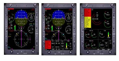
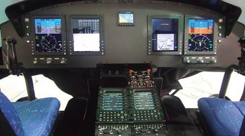
SAGEM GLASS COCKPIT
SAGEM Cockpit Display System
SAGEM has a fully certified helicopter glass cockpit which includes the following:
- 3 each ICDS-10A Integrated Cockpit Displays
- 2 each PFD-35AAir Data Computers
- 2 each EMM-35H Engine Modules
- 2 each Tach Generator Interface Units
- 2 each Signal Interface Units
- 1 each Fuel Quantity Signal Conditioner
- 4 each Pressure Transducers
- 2 each Crossbow AHRS Computers and Remote Magnetometers
- 1 each Structural Bracket Kit
- 1 each Wire Harness Kit
- 1 each Instrument Panel (3 sections)


GARMIN GLASS COCKPIT
Garmin Glass Cockpit System has been specifically designed to meet the requirements of twin engine helicopters and is optimized for IFR, Category A & B, and JAROPS-3 compliant operations. The system is highly flexible and configurable to meet various operating and customization needs. The system takes advantage of the latest in display, computer processing, and digital data bus technology to provide a high degree of redundancy, reliability, and flexibility.
BASIC FEATURES and will vary depending on model
- All primary flight and navigation instrumentation
- Presentation of flight director and autopilot status
- Engine and rotor drive system indications
- Electrical, hydraulic, and fuel system monitoring
- Crew alerting system (warnings / cautions / advisories and aural alerts)
- Navigation route mapping display
- Presentation of optional Traffic Collision Avoidance Symbology (TCAS)
- Presentation of optional weather radar or search radar information
- Presentation of optional Forward Looking Infrared (FLIR) / Enhanced Vision Systems (EVS) video display (either NTSC or PAL standard)
- Presentation of general color video display or digital map display (NTSC or PAL standard in either S-Video or Component RGB video)
- Presentation of electrical schematic, fuel schematic, and weight and balance summary information
- Presentation of automated power assurance, Category A performance, and hover performance calculations
- Presentation of maintenance and diagnostic data
Customers can choose from Garmin G500H, G600H, G1000H, or G5000H Systems
GARMIN GPS
GNS-430AW/530AW/ or GTN 650/750
BASIC FEATURES and will vary depending on model
- Complies with WAAS TSO C146a
- Terrain database for terrain awareness is standard
- WAAS GPS receiver allows for primary navigation and vertical guidance for LPV, L/VNAV, and LNAV+V approaches
- Combines 16 watt VHF communications transceiver, VHF navigation and UHF glideslope receivers, 12-channel GPS receiver with color moving map
- WAAS and LAAS compatible GPS receiver
- 760 channel VHF comm with 25khz spacing; software configurable for 2280 channels (8.33 kHz spacing) for Europe
- Provides both course deviation and optional roll steering outputs to aircraft flight guidance systems which will enable ARINC 424 lateral guidance procedures including IFR arrivals, departures and approaches
- Automatically will nominate appropriate VOR and localizer frequencies for VHF navaid
- Sends correct ATIS, approach, clearance, tower or ground control frequency to the comm radio at the touch of a button
- 16-color, active-matrix LCD measuring approximately 2" high and 3" wide with a resolution of 128 by 240 pixels
- Cartographic database displays geopolitical boundaries, federal interstate highways, state routes, major local thoroughfares, plus railroads, rivers, coastlines and lakes
- Can be interfaced to main indicators such as KI-202/203/204/206/208/208A/209/209A
- Can be interface to Bendix/King RMI units such as KI-229 and KNI-582
- Can tune most panel mount DME and remote mount DME units
- Interfaces to ARINC 429 EFIS systems such as Sandel SN3308 and Bendix/King EFIS 40 & 50
- RS-232 and RS-422 serial ports for interfacing
- ARINC 429 digital output (GAMA standard) for left/right analog course deviation, ng, encoded or greycode altitude, and basic fuel flow sensor links
- Fuel Flow page configurable to allow for simultaneous display of left and right engine fuel flows
- ARINC 429 digital output compatible with some autopilots which can accept ARINC 429 roll- steering information
- ARINC 429 output data can be used with digital to analog adapter such as Allied Signal KA- 90 to produce roll-steering signal used by autopilots systems requiring analog signal
- Accepts RS-232 fuel flow data from external sources
- 28 Volt or 14 Volt operation
- TSO'd
- Interfaces to BF Goodrich WX-500 Weather Mapping Sensor and Skywatch Traffic Advisory System for combined moving map display with nav data and weather/traffic information
- Interfaces to Ryan 9900B / 9900BX TCAD and Goodrich Skywatch to display traffic information


GARMIN TCAS II
The Leading Edge of Traffic Surveillance
- A fully TCAS II/ACAS II Change 7.1 compliant system
- Issues Resolution Advisories to help clear conflicts
- Displays vertical speed constraints and climb/descend info
- Active traffic is enhanced with ADS-B "In" for a comprehensive traffic picture
- Upgradeable for NextGen/SES System applications
The GTS 8000 brings new levels of safety to aircraft by not only providing a crystal-clear picture of potential traffic threats, but also by issuing maneuver commands that direct pilots on how to best clear these conflicts. As a Change 7.1 compliant solution, the GTS 8000 meets the standardization requirements that will be implemented in most countries.
HONEYWELL TCAS II
The Rockwell Collins TCAS-4000 (TCAS II) improves safety with total situational awareness of impending traffic conflicts, including the display of resolutionary information for immediate threats. The system tracks all Mode C and Mode S transponders and provides range, relative bearing and altitude information for the up to 30 aircraft that pose the greatest threat of collision. It incorporates Change 7 logic as standard and is software upgradeable to Change 7.1.
TCAS-4000 consists of a TTR-4000 TCAS transmitter/receiver, one or two TRE-920 TCAS directional antennas, two TDR-94 MODE S transponders, a variety of control panels and a wide variety of traffic display options. Resolution Advisory commands appear on the two vertical speed indicators or the vertical speed display fields of integrated electronic flight display systems.
Features & Benefits
- Enhances crew situational awareness: Real-time visual display of surrounding traffic situation and potential collision threats provides flight crew with improved safety.
- TCAS II features: Change 7 incorporated as standard and Change 7.1 is field loadable; ACAS II compliant.
- Transponder features: TCAS II compliant; data link capable for TCAS II crosslink and ATC data communications; ICAO Level 2A capable.
- Growth capable: An efficient receiver architecture allows for growth for future applications.
- Innovative architecture: Provides increased efficiency to avoid transponder overload.
- Extensive IO capability: Contains both analog and digital system interfaces for universal application and fleet commonality.
- Flexible interface options: Provides a wide variety of display and control options and interfaces with single or dual Mode S transponders (including the Rockwell Collins TDR-94).
- Maintainability features: Data load for shop or on-aircraft software revisions; diagnostics for easy fault isolation and shop maintenance; plus extensive internal diagnostics.


STANDARD AVIONICS
Communication
- Intercommunication System NAT 301 065 or (Andrea ARC 301-6W)- 4 Station
- VHF / NAV #1 & #2 KX-165A (Honeywell) or KTR 908 (Honeywell) or GNC 255 (Garmin)
Navigation
- ADF – KR-87 or KDF 806 (Honeywell)
- DME - KDM-706A (Honeywell)
- Radar Altimeter KRA 405B (Honeywell) or GRA5500 (Garmin)
- Compass – KCS-55A (Honeywell)
- GPS – KLN-900 (Honeywell) or GNS430/530 GTN 650/750 (Garmin)
- Transponder – KT-76C (Honeywell) or Garmin GTX 327 Mode C/GTX 330 Mode S/GTX-33H ES Mode S
- Traffic Avoidance System - TAS605/620 -w- Mutable Audio (Avidyne) or TCAS II (Honeywell)
- Weather Data Link - GDL-69A (Garmin) & XM Radio -w- Remote or Telephonic RDR-1600, Airborne RDR-2000 or Primus 701A (Honeywell)
Optional
- ELT - A406 - 2HM (Artex)
- ELT - C406N-HM / 3 Freq. -w- GPS Interface (Artex)
- UHF - KTR-909 (Honeywell)
- Wulfsberg RT5000
- Tetra Radio MDT-400
- HF Radio
- Satellite Phones (Iridium)
- Hand-Held GPS Garmin
- Hand-Held Radio (s) ICOM
- Standby Attitude
- Standby Altitude
- Standby Airspeed
- Standby Compass (Magnetic)
- Standby OAT
Many variations can be configured to customer requirements and preferences.
ADF KDF-806
Designed to offer superior performance and reliability, the all solid-state BendixKing KDF 806 is the acknowledged standard in remote-mounted ADF systems. Incorporating “coherent detection” technology, the KDF 806 is able to select weak or distant signals with a high level of accuracy.
This capability helps reject interference and eliminate bearing errors, even during thunderstorms, to give you reliable ADF tracking. All ADF frequencies, from 190 kHz to 1799 kHz (with an option to include marine frequencies up to 2182 kHz), are generated by a digital synthesizer.


VOR KNR-634A
The KNR 634A digital VOR/LOC/GS/MB receiver features 200-channel VOR/LOC, 40-channel glideslope and marker beacon with XYZ RMI. Also includes KFS 564A frequency selector which simultaneously displays active and standby frequencies in gas discharge numerics. The KNR 634A accepts ARINC 429 channeling and provides ARINC 429 outputs for use with EFS 10 and ARINC 429 based systems. TSO'd.
DME KDM-706A
Known for its reliability, the KDM 706A all solid-state distance measuring equipment (DME) features 252 channels and 250 watts. It accepts direct DME channeling from BendixKing serial, 2x5, and ARINC 429 serial tuning formats. It has outputs for ARINC formats 568 and 429, analog pulse pairs, and analog rate pulse, plus BendixKing Serial Data for DME indicators.
Compatible with an electronic flight instrument system (EFIS), meaning that the KDM 706A's self-test sequence is on a 3 second interval as opposed to the 1 second interval of other units.
Includes a KA 60 antenna, installation kit, and DME indicator.
Available with KDI 572 indicator (28V or 5V) and KDI 574 indicator. 18 to 33VDC operation. TSOd.


AM KTR-908
Providing superior two-way AM voice communications, these units were specifically designed for international governmental, military and paramilitary applications, and have already been specified for use in U.S. Air Force and U.S. Navy training programs.
The all-solid-state unit accesses frequencies from 225.000 to 399.975 MHz in 25 kHz increments and is specifically designed for low maintenance and high reliability. The KTR 909 scans other frequencies when the unit is not in use.
The KFS 599A control head is used as an interface for the KTR 909. The control head features 20 user programmable channels an easy-to-read gas-discharge display or Night Vision Goggle (NVG) compatible display.
TRANSPONDER NXT-800
FEATURES
- The light-weight NXT-800 transmits ADS-B Out data from your aircraft to other nearby aircraft and Air Traffic Control (ATC)
- DO-260B compliant to meet FAA/EASA NextGen mandates, while transmitting a more precise position, speed and intent data
- Meets Air Transport, Business Jet and Helicopter demands with 3 size options that are form factor replacements for the XS-950 (4 MCU)
- RCZ-852 and ¼ ATR Short
- Elementary & Enhanced Mode S surveillance compliant
- Maximum reliability with built-in test and self-test capabilities
- Compatible with all ARINC 735B/735A/735 TCAS II systems, including ACSS TCAS 3000SP,TCAS 2000, T2, CAS® and T3 CAS
- AC or DC power options


ADS-B LYNX NGT-9000
The Lynx® MultiLink Surveillance Systems (MSS) is a single box avionics solution packed full of ADS-B benefits. The Lynx family includes four models, ranging from an ADS-B Out only unit with WiFi display options for Persona Electronic Devices (PED) as well as models for display of ADS-B information to dedicated cockpit displays (MFDs). The most notable model is the Lynx NGT-9000 - an intuitive touch screen display that is a form-factor replacement for existing transponders. The NGT-9000 offers an extensive features list and is the most logical choice for pilot’s looking to take full advantage of the ADS-B NextGen flight environment.
The Lynx NGT-9000 series provide 1090ES (Mode S Extended Squitter) ADS-B Out as well as 1090Mhz and 978Mhz (UAT) ADS-B In. This provides ADS-B traffic (ADS-B, ADS-R and TIS-B) and FIS-B input. L-3 NextGen Active Traffic® and/or ADS-B antenna diversity is an available option. Panel mount (NGT-9000) and remote mount (NGT9000R) versions are available. All systems provide 14 CFR 91.227 compliance. A WiFi interface module is available for connectivity to iPad® and AndroidTM devices with applications such as WingX Pro and SkyRadar (other apps pending). All Lynx MSS models incorporate a rule compliant position source (WAAS GPS) requiring no external GPS connections.
One of the primary benefits of the ADS-B environment is the traffic information it provides. The Lynx NGT-9000 offers flexibility to display traffic on the unit itself, as well as other panel mounted avionics that use the popular ARINC 429, RS-232 or RS-422 protocols. The NGT-9000 model features an option for an in-line WiFi transmitter, enabling pilots to view ADS-B traffic on their PED (iPad) using a compatible app. Since the Lynx NGT-9000 receives simultaneously on both 1090Mhz and 978Mhz, pilots will receive ADS-B traffic regardless of altitude or geographic location.
While ADS-B traffic is comprehensive, there are limitations to the service including line of sight to station, non-equipped areas, GPS signal integrity and non-participating aircraft. The Lynx NGT-9000 has the option to be equipped with the L-3 NextGen Active Traffic® system. This enablement blends ADS-B with active traffic data, providing an uninterrupted display of aircraft equipped with Mode A, C and S transponders. Adding NextGen Active Traffic also enables extended aural alerting of intruder aircraft position such as “Traffic, 1 O’clock High, 2 Miles.” Existing SkyWatch® owners can opt to re-use the system’s antenna and cables. The L-3 NextGen Active Traffic enablement is built into the NGT-9000+, eliminating the need for an external box, saving weight and installation costs.
The Lynx NGT-9000 includes subscription-free weather data such as METARs, AIRMETs, SIGMETs and NEXRAD information overlaid on a moving map. A second map page shows Winds and Temps Aloft data. This arrangement allows the pilot to quickly page through graphical weather screens, viewing large amounts of data without overloading a single page. A touch of the finger on the graphical weather map brings up corresponding textual data of the highlighted station or weather icon. A settings page allows the pilot to further customize the weather data pages in both detail and range.
With the Lynx family of ADS-B products, you will receive up to the minute broadcast information regarding airports, Notice to Airmen (NOTAMs) and Temporary Flight Restrictions (TFR) in graphical and textual form. Similar to the weather map, touching an airport or zone icon on the graphical side of NGT-9000 map brings up its corresponding textual data. This data is useful in all phases of flight, aiding the pilot in planning proper routes and informing them about their departing and destination airports.
LYNX NGT-9000 FEATURES
- Mode S Extended Squitter (ES) transponder with intuitive touch screen interface
- Dual Mode 1090ES ADS-B Out plus 1090 and 978 ADS-B In
- Designed for 14V and 28V installations
- Patented Lynx Tail provides Flight ID, aircraft type and ground speed data of other ADS-B traffic
- Internal rule compliant position source (WAAS-GPS)
- Moving map including TFRs, airport databases and NOTAMs
- Subscription-free ADS-B graphical and textual weather including NEXRAD, METARs, Winds & Temps Aloft, AIRMETs and SIGMETs
- Customizable layouts and information per pilot preference
- Faceplate data port for maintenance personnel access to setup menus, software updates and option enablements via laptop
- Options available for internal L-3 NextGen Active Traffic, Antenna Diversity, PED (iPad) WiFi connectivity and Remote Mount models


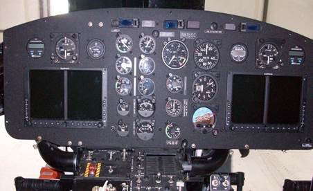
NVG COMPATIBILITY
SWFA is pleased to be able to offer our fully engineered digital cockpit upgrade and modernization solution. This cockpit upgrade is currently complete and in operation and is fully NVG compliant. The engineering has been completed and the system will come with installation manuals, Flight Manual Supplements and instructions for continued airworthiness (ICA’s). We are offering the installation in a NVG Kit form which will include all components and wiring necessary for installation.
SWFA manufacturers new instrument panels to meet each customers’ requirements. Panels are manufactured on CNC machines using stronger materials than the original.
STANDARD INSTRUMENT PANEL AND INDICATORS
Pilot and Copilot
Airspeed, Altitude, Altimeter, Attitude, VSI
Radar Altimeter - KRA-405, KNI-416 (Honeywell)
HSI - KI-525 Pilot/ KI-825 Co-Pilot (Honeywell)
RMI - KI-229 (Honeywell)
Turn and Slip
ADF
DME
Center
Dual Tachometer (Nr & Nf)
Torque
Tachometers (Ng)
Exhaust Gas Temperature
Engine Oil Pressure & Temperature
Transmission Oil Pressure & Temperature
Fuel Pressure
Fuel Quantity
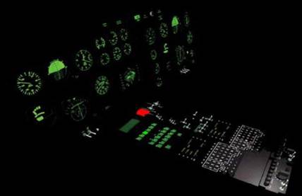
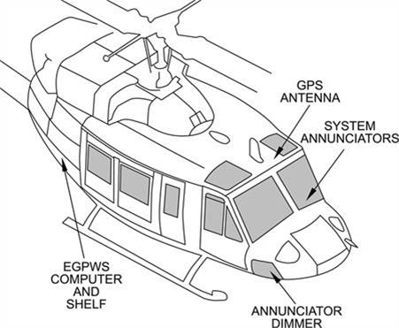
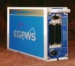
EGPWS
Honeywell's Enhanced Ground Proximity Warning Systems (EGPWS): The state-of-the-art MK XXII EGPWS is a full-featured HTAWS system with highly advanced safety functions for IFR-equipped helicopters with a radio altimeter. This system exceeds the FAA TSO-C194 requirements. In addition to HTAWS required modes, it includes several GPWS modes and unique callouts for excessive bank angle, tail strike protection, and autorotation.
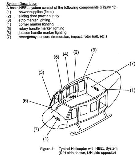
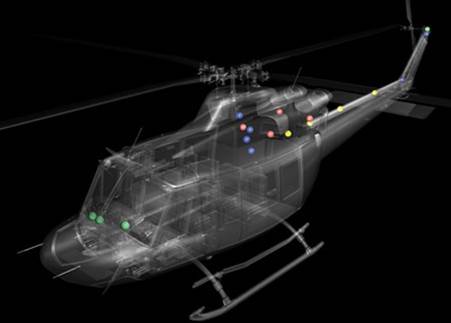
HEEL
Helicopter Emergency Egress Lighting Systems (HEELS) identifies emergency escape hatches, exits and push-out windows by illuminating their perimeter to guide you to safety during emergency situations.
Automatic illumination occurs if aircraft power is lost or when the lighting system water sensor becomes immersed in water. HEELS can also be manually illuminated using a three mode ON, OFF, ARMED cockpit switch. HEELS is also a battery-operated independent lighting system. A typical HEELS installation consists of an array of light emitting diodes on substrate placed around escape hatches or doors. The system has two water sensors, each of which will activate lighting upon immersion. An optional aircraft Permanent Magnet Generator (PMG) interface unit monitors rotor rpm and interfaces the HEELS to the aircraft. The system is activated upon signal loss. When the rotors fall below a threshold rpm, the HEELS will automatically illuminate. The Control Unit consists of an electronic module with a removable battery pack, which automatically recharges during flight.


VIBRATION MONITOR
The Helicopter Vibration Monitor (HVM) Kit and Altair Engine Trend Monitor System provide drive train health and engine monitoring to improve aircraft serviceability and maintainability between regularly scheduled inspections and overhaul periods. A control head located in the pedestal provides the primary flight crew interface to the HVM. A pedestal mounted USB port allows the flight crew to transfer data between the aircraft and a PC-based ground support station. An Ethernet connection provides means for maintenance personnel to connect to the ground support station. HVM diagnostics facilitate vibration- related maintenance functions such as main rotor track and balance, tail rotor balancing, main input drive shaft balancing and turning of the instrument panel Frahm absorber. Enhanced vibration diagnostics allow maintenance personnel to detect faults within the main rotor system, tail rotor drive system, engine accessory gearbox and combining gearbox. Built-in test features simplify system troubleshooting.
HONEYWELL HUMS KIT
The HUMS Kit provides the Helicopter a comprehensive airframe, rotor, engine and drive system vibration monitoring capability, and aircraft data recording supports customer flight data monitoring (FDM) programs. The HUMS Kit is designed to conduct routine vibration management functions, with no changes required in the mandatory maintenance functions of the Maintenance Manual. The system utilizes its vibration monitoring capability to make discretionary rotor and balance adjustments. No pilot interface is required during flight operations. Data downloads are manually commanded by pressing the LED array switch located on the PBA panel in the center pedestal.


FORESIGHT MX HUMS KIT
Hums Kit
Foresight MXcombines onboard sensor and avionics data, automated data transfer via WiFi/cellular, and powerful algorithms in the cloud. The result is a predictive dashboard available from any browser.
- Optimize Rotor Track &Balance
- Flight Data + Exceeding Monitoring
- Engine + Drivetrain Health Monitoring
| FORESIGHT FEATURES, ATTRIBUTES, & SPECIFICATIONS – 204/205/212/412
CORE FEATURES Machine Condition Component vibration monitoring |
|||
| Monitoring | Engine performance monitoring | ||
| Dashboard of component and engine Health Indicators | |||
| Diagnostic capability via Condition Indicator drilldown | |||
| Prognosticcapability providing RUL for trending components | |||
| Fault validation capability via raw sensor data | |||
| Flight Data Monitoring | Data from avionics via ARINC 429 or analog interface | ||
| Track & graph missions on 37+ parameters; 60+ on download | |||
| Automatic digital capture of OEM exceedances | |||
| Automatic capture operator defined exceedances | |||
| All data exportable into X-Plane | |||
| AC 135-14B HEMS HFDM compliant | |||
| Rotor Track & Balance | Automatic in-flight regime recognition and acquisitions | ||
| Optimized RTB adjustment (WGTS, PCRS, TABS) available postflight | |||
| Adjustments can be modified, constrained, or overridden | |||
| Main and tail rotor balancing | |||
| 1/rev and 2/rev | |||
| SYSTEM-WIDE ATTRIBUTES
Accessibility Interpretability Data Transfer Updatability Certifications Software Integrations Data Export Alerting Aircraft Support |
Any-device, Anywhere access via cloud+browser architecture | ||
| By maintainer (not dedicated expert) via intuitive dashboards | |||
| Automatic postflight upon cooldown via cellular or WiFi | |||
| HW updates over the air, SW updates in cloud | |||
| STC | |||
| Yes via API’S | |||
| Yes, via export buttons | |||
| Yes, via Email or SMS | |||
| Digital or Analog | |||


204/205/212/412 Foresight MX
The GPMS Foresight MX Remote Monitoring Health and Usage Monitoring System (HUMS) is the most advanced health and condition monitoring system on the market today, combining data acquisition, transfer, analysis, and display.
Continuously monitor your fleet from any device and from anywhere, through our proprietary cloud-based software. Foresight MX’s smart sensors uncover when components are starting to wear and our prognostic algorithms display when maintenance may be required.
The Foresight MX combines mechanical machine condition monitoring (MCM), rotor track and balancing (RTB), and helicopter flight data monitoring (HDFM) all in one solution with a STC'd weight of 3.36 kg.

GPMS 204/205/212/412 Foresight MX and Honeywell HUMS Comparison
| Feature | Honeywell | GPMS | Why It Matters |
| System Architecture | Ground Station + Aggregation Server | Cloud-Based | Remote and faster access from any browser-enabled device and any location |
| Data Transfer | Manual via usb stick | Automated via onboard wifi/cell | Regime detection + WiFi and LTE capabilities for quicker and automatic remote access |
| Usability | Specialized Interpreter needed | All Members of your team | Intuitive, modern UI dashboard for all users |
| Accuracy | Data Processing in the main signal processing unit (MSPU) | Data Processing at sensor level, onboard control unit (OBCU), and in the cloud | Distributed processing for faster acquisitions and more data, resulting in improved data accuracy |
| Updates | Static | Future Proof | Secure, over-the-air updating capabilities keep the system up-to- date and modern. |
| Weight | ~9.07kg | 6.52kg | Bused architecture uses less wire + lightweight sensors, providing weight savings |
Our Differentiators
Competitors are years behind with legacy products lagging in accuracy, usability, weight, & cost.

FLIGHT DIRECTOR
Some Rotorcraft utilizes the Honeywell SPZ-7600 digital Automatic Flight Control System (AFCS), providing 3-axis or 4-axis flight director capability. The rotorcraft can be equipped readily allowing upgrade to 4-axis which provides the additional features of yaw trim, altitude pre-select, simultaneous vertical and speed coupling, automatically decelerating approaches, radar altitude hover hold, and hover velocity assist.
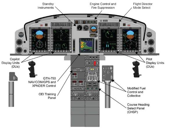
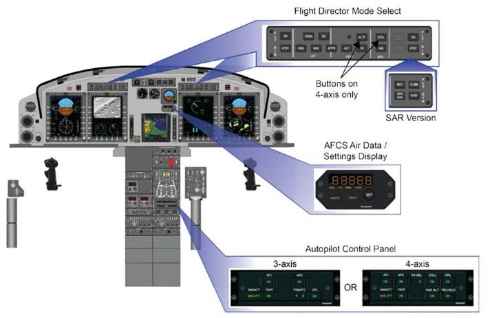
CV/FDR
The Cockpit Voice and Flight Data Recorder (CV/FDR) is an “on-condition,” line-replaceable unit that simultaneously records both cockpit voice and flight data. This CV/FDR is capable of recording a minimum of 25 hours of flight data and two hours of audio. Audio inputs are provided from three separate channels. The CVR simultaneously records all three channels, converts the audio into a digital format and stores the data in solid-state memory. Flight data is recorded in flash memory and segregated from the cockpit voice data. Flight data may be downloaded to ground station equipment in approximately five minutes. A ground support equipment interface connector is provided and easily accessible. A pedestal mounted cockpit control unit enables CV/FDR test and recorded audio monitoring. The recorder is JAR-OPS 3 approved.
Installation requires additional specialized test equipment (which is NOT included in this kit) in order to comply with the installation requirements. This equipment can either be purchased or leased.


WEATHER RADAR
With its advanced solid-state transmitter design eliminating the need for life limited magnetron tubes, the GWX 70 — and GWX 70H that's been made more rugged for helicopter operations — comprises the very latest and most reliable technology in onboard weather radar.
- Scan with Doppler Accuracy
Bringing full-color storm cell tracking to your compatible Garmin multifunction display, this Doppler-capable weather avoidance tool combines excellent range and adjustable scanning profiles with precision target definition — for accurate, easy-to-interpret, weather analysis in the cockpit. With pilot-adjustable horizontal scan angles of up to 120°, you can easily focus scanning on the areas you want to watch, while vertical scanning lets you focus on storm tops, gradients and cell buildup at various altitudes. Plus, Weather Attenuated Color Highlight (WATCH™) can identify areas beyond the radar's capability that may contain even more hazardous areas of precipitation. - Reduce Pilot Workload
On compatible displays, altitude compensated tilt in the GWX 70 reduces your workload by needing to manually adjust the radar’s tilt; simply set it once to the tilt angle you want, and it will automatically adjust with any change in altitude. Also, when interfaced with your aircraft’s analog gyro or AHRS system, the GWX 70 offers full radar stabilization to 30 degrees of pitch and roll. The GWX 70 also has a ground mapping mode that can assist in a number of applications -- including navigation. Ground mapping mode provides a real-time depiction of the terrain below you. - Experience Solid-State Reliability
With its digital design, the GWX 70 provides reduced power consumption and extended life when compared to previous generations of magnetron-based radars. While magnetron tubes degrade or burn out over time, the solid-state technology in the GWX 70 maintains a consistent weather picture its entire lifecycle – all while only using 40 W of power. What’s more, the all-in-one antenna/receiver/transmitter unit is available in 10", 12" and 18" radomes, so it easily installed on a wide variety of aircraft configurations. - Upgrade to Advanced Features
The GWX 70 you buy today is prepared for the technologies you might need tomorrow. You can unlock a wealth of new functionality in your GWX 70, such as ground clutter suppression*, which identifies radar ground returns and removes them from the display – taking the guesswork out of interpreting what's on your screen. And optional turbulence detection* can determine areas of turbulence that might contain particulate, like rain or hail. These capabilities are available through simple software upgrades, eliminating the need to purchase new hardware in the future.
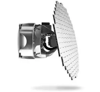
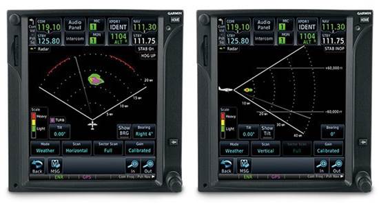
ART 2100 Avionic Upgrade
Setting a new standard in value and performance, the RDR 2100 Digital Weather Radar provides a vertical picture of a pilot-selected cross- section of the storm, offering the best view available to general aviation. The simple press of a button allows you to analyze a storm segment vertically, giving you the information you need to determine the scope of the storm.
You can examine the angle of the cell's leading edge to determine direction of movement, monitor the tops of cells to see how quickly a storm is building, and easily distinguish between ground and weather returns. The system is fully stabilized to +/- 30° combined pitch and roll, and antenna stabilization keeps your screen clear of ground returns during moderate aircraft maneuvers. You can choose between two antennas, a 10-inch or 12-inch, to fit a wide variety of airframe applications.
The RDR 2100 uses intuitive colors (green, yellow, red, magenta), and six ranges (10 nm to 320 nm) to depict the weather intensity, creating a clear picture of the weather and making it easy for you to avoid danger. The horizontal scan provides an angle of 120°; the vertical scan an angle of 60°. Using Sensitivity Time Logic, the system can correlate target distance with intensity, and its attenuation compensation reduces shadowing.
The system is fully Electronic Flight Instrument System (EFIS) compatible using ARINC 429 and ARINC 453 data busses. It also features a Multi- Function Display (MFD) interface, fault annunciation, TILT readout on display, and independent dual indicator operation.

OVERHAUL MAJOR COMPONENTS
Overhauls Major Components-Included
| Item # | Type | Mod | Benefit |
| 1 | DT&RS | Overhauled hub | Improved lift to 12,500 lb. / 5,669 kg internal; 12,500 lb. / 5,669 kg external GW |
| 2 | DT&RS | Overhauled Main rotor transmission | Increased horsepower to 1,370 HP |
| 3 | DT&RS | Overhauled Swashplate Assembly | Improved lift to 12,500 lb. / 5,669 kg internal; 12,500 lb. / 5,669 kg external GW |
| 4 | DT&RS | Overhauled main and tail rotor drive shaft and coupling | Increased horsepower to 1,370 HP |
| 5 | DT&RS | Overhauled tail rotor | Additional tail rotor authority and efficiency at higher altitudes |
| 6 | DT&RS | Overhauled 90° gearbox | Additional tail rotor authority and efficiency at higher altitudes |
| 7 | DT&RS | Overhauled 42° gearbox | Increased horsepower to 1,370 HP |
| 8 | DT&RS | Overhauled hydraulics system | Improves cyclic control by raising the operating pressure to 1,500 PSI |
| 9 | DT&RS | Twin T53-L-13B engines install | Increased horsepower with increased efficiency at higher altitudes, increased to 4,000 TBO |
| 10 | Airframe | Overhauled oil cooler and blower | Improved cooling for T53-L-13B engine |
| 11 | Airframe | Overhauled airframe | Increased strength for 1,370 HP and 56.5 PSI torque |
| 12 | Airframe | Overhauled lift beam and main beam and pylon | Increased strength for 1,370 HP and 6,000 lb. / 2,268 kg cargo hook capacity |
| 13 | Airframe | Overhauled cross tube tunnel | Increased strength and fatigue capabilities for 12,500 lb. / 5,669 kg internal GW |
| 14 | Tailboom | Overhauled tailboom for additional torque requirements | Increased strength for 1,370 HP and 56.5 PSI torque |
| 15 | Tailboom | 412 vertical fin | Reduced flight loads and better crosswind performance |
| 16 | Tailboom | Boundary Layer Research Inc. tailboom mods | Improves cyclic control |
| 17 | Electrical Avionics | Optional electrical and avionics | Options include electrical rewire, glass cockpit STC and avionics suites |

WEB/SPAR REPLACEMENT
Replacement of the BHTI Vertical Fin Web/Spar with the New BELL 412 Helicopter Vertical Fin Web/Spar Assembly is considered by the Federal Aviation Administration (FAA) a major repair and therefore requires “competent and experienced” personnel. SWFA holds Federal Aviation Administration (FAA) approval under its Repair Station Certificate for the replacement of the fin spar/web on the following aircraft: UH-1B, UH-1H, UH-1L, UH-1F, UH-1P, 204B, 205A-1, 212, and 412. This modification is a Federal Aviation Administration (FAA) - Means of Compliance (MOC) approved terminating action for the spar Airworthiness Directive (AD 99-25-12, AD 93-02-07).

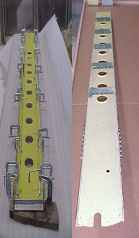


LED STROBE LIGHTS
LED Strobe Lights-Included
71080 Series beacons are FAA TSO compliant self- contained LED Anti-Collision lights (Ref. Class I - 150 effective candlepower). They are designed to replace a range of products. Refer to models and descriptions below.
Models -01, -04, -05, -14, -15, -20, -51, -55: Ship
with 12” Flying Leads. Models -07, -17, -08, -18:
MS3102R10SL-3P Connector. Models -04, -14, -08, - 18: designed to replace existing beacons using 5- Hole mounting pattern on a 4.656 dia. bolt circle (Whelen 70285 series/7090501 series or 70900 with A440 adapter). Models -05, -15, -07, -17: 3 ¾” opening designed to fit inside an A440 mounting adapter, mounting holes to fit in place of rotating beacons, Whelen Model HRCFA, or 7090004, -05 series LED beacons.
AUGMENTED TAIL ROTOR SYSTEM
Augmented Tail Rotor System
The conceptual design system uses a fan inside the tailboom to build a high volume of low-pressure air, which exits through slots and creates a flow of air along the tailboom utilizing the Coanda effect. This system augments the existing conventional tail rotor. The boundary layer changes the direction of airflow around the tailboom, creating thrust opposite the motion imparted to the fuselage by the torque effect of the main rotor. Augmented directional yaw control is gained through a vented drum at the end of the tailboom by the direct jet thruster. The system offers quiet and safe operation.
The anti-torque fan being considered is an axial fan with thirteen variable pitch blades. The fan provides anti-torque by furnishing variable flow of low pressure high volume air through the tailboom and thrusters. The fan operational rpm in flight at 100% power is 5,412 rpm. At 104% power, the fan rpm is 5,628.
Design Parameters:
- Fan Rotation Direction-Top blade afterward (TBA) direction makes the inflow dynamic pressure distribution uniform, so that aerodynamic and acoustic attributes are better.
- Blade Diameter- If large, low required power and high control power. If small, low weight and low hub drag. Diameter of the existing fan ranges 0.7m to 1.37m
- Fan Tip Speed- In forward flight, blade is unloading. Fin makes most of the anti-torque force. Advancing side problem is not critical. Around the main rotor tip speed is usually employed.
- Solidity-Ct/σmax and maximum thrust required determine a solidity. Range 0.5 to 0.56.
- Number of Blades-Aspect ratio is a main parameter. Even number is better for uneven blade spacing because of dynamics. Blades number ranges 8 to 12


TECHNOLOGY DEVELOPMENT
- Evolutionary, not revolutionary
- UH-1 technology from 1960s and current advanced technology
- Technical library
- Five patents
- Three generations experience
- New materials, mechanical enhancements
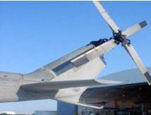
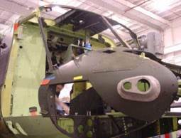


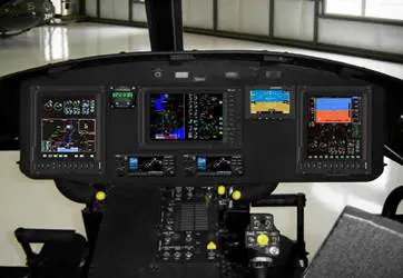
AIRFRAME MANUFACTURING

MANUFACTURING AND DEVELOPMENT QUALIFICATIONS
- FAA/CAA certified Type Certificate H6SO
- Authorizes SWFA to manufacture helicopters to FAA/CAA approved specifications
- Only company with approvals for upgrades, modifications and maintenance of the SW204/205/210 models under certificates
- Only company FAA/CAA approved for 212/412 upgrades under Type Certificate
- In process application to CAA for addition of SW205T, SW212, SW412, and SW429 to TC
INTELLECTUAL PROPERTY
- Patent number 5,375,977, ROTOR BLADE RECORDER SYSTEM.
- Patent number 5,007,167, BLADE MODIFICATION TOOLAND PROCESS.
- Patent number 5,377,934, HELICOPTER CONVERSION.
- Patent number 5,791,594, DUAL ENGINE SW205.
Patent # 5,375,977, ROTOR BLADE RECORDER SYSTEM
")
Patent # 5,007,167, BLADE MODIFICATION
Patent number 5,377,934, HELICOPTER CONVERSION

Patent # 5,791,594, DUAL ENGINE SW205
")
Patent # 337,301 Helicopter Gunship

U.S.A. TYPE CERTIFICATE H6SO

SPAIN TYPE CERTIFICATE 41-I

DR TYPE CERTIFICATE H6SO

DR PRODUCTION CERTIFICATE HI-101

AUSTRALIA TYPE ACCEPTANCE CERTIFICATE R36

SA TYPE ACCEPTANCE CERTIFICATE SW204/205

REPAIR STATION CERTIFICATE UL4R574M

TECHNICAL LIBRARY
- Maintains a large technical library which includes:
- 5,000+ Engineering Drawings Of Helicopter Models 204, 205, 212 And UH-1 Series Aircraft
- Manufacturing details as furnished to U.S. Government
Bell used all of the above information during FAA certification of the Bell 204B, 205A/A-1, 210, 212
- Reference Manuals, Technical Drawings, Specifications, Maintenance Manuals, Illustrated Parts Manuals, Component Overhaul Manuals, Test Reports and Fatigue Test Data
- All the above Bell data was identified and released to U.S. Government as “contract data” and is legally “Public Domain” information.
RESEARCH & DEVELOPMENT
SW205: Single Engine, Dual Composite Blades, VFR Cockpit SW205T: Dual Engine, 2 Composite Blades, IFR Cockpit SW212: Dual Engine, 2 Composite Blades, IFR Cockpit
SW412 & SW429: Dual Engine, 4 Composite Blades, IFR Cockpit
Key Enhancements:
- Glass Cockpit
- Integrated Communications, Navigation, Flight Path and Engine Instruments
- Engine/Transmission
- Honeywell T53-L-703/T5317 or PT6C-67D Engines
- Alternative Engines
- Oil Debris Detection System
- Centrisep or Donaldson Inlet Barrier Filtration System
- Upgraded Transmission And Cooling Systems
- Wide Chord Composite Main Rotor Blades
- Improved Kaflex Shaft Between Engine And Transmission
STRATEGIC OBJECTIVES
Project Critical Objectives
- Establish locally controlled, CAA approved, design for single and twin engine helicopters
- Provides growth path to all local content (including engines, transmissions, rotor blades, avionics)
- CAA Certified Manufacturing Facility for local production of CAA Type Certified single and twin engine helicopters
- Certifications to include:
- Aircraft CAA Type Certification (TC) and Supplemental Type Certification (STC) for local model variants
- Production Certification (PC) & Parts Manufacture Approval (PMA)
EXPANSION STRATEGY
Pathway to Production

TOP LEVEL PROGRAM SCHEDULE

SUMMARY
- SWFA can provide a cost effective, powerful helicopter for:
- Transport
- Air Ambulance
- Search and Rescue
- Parapublic
- External Load
- SWFA can also provide Field Support Services
- Pilots and maintenance personnel to train your people
- Logistics support services (spare parts, consumables) and personnel to help you setup a remote operating location
ARMAMENT
ALL DIRECTORS AND STAFF ARE COMMITTED TO THE IMPORTANCE OF BUILDING STRONG BUSINESS RELATIONSHIP BASED ON THE HIGH LEVEL OF OUR PROFESSIONAL SERVICES.
WE CAN PROVIDED EXAMPLES OF VARIOUS WEAPONS SYSTEMS USED ON THE SW SERIES AND UH-1 SERIES HELICOPTERS.